IsoDrill Frac Plug

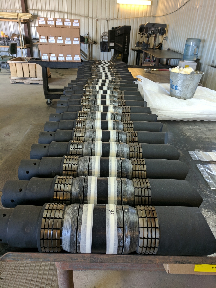
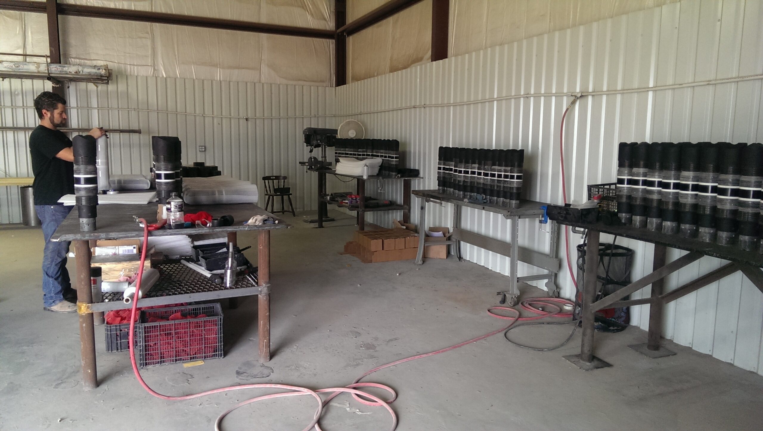
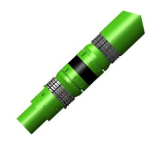
The IsoDrill composite BRIDGE PLUG, caged ball and ball drop (flow thru) frac plug provide a means to isolate multiple zones during high pressure stimulation frac operations. The Bridge Plug is designed to temporarily plug a well or to provide isolation from either above or below the isolation point. The Ball Drop (flow thru) Frac Plug allows for fluid to flow from above and below the isolation point until the ball is pumped down from the surface and seated on top of the composite frac plug. The operator can pressure up against the frac plug to achieve isolation. Due to the composition of the material, the plugs can be easily milled and circulated back to surface. Please contact us for more information about the Iso Drill.

Gallery

Application

  • Single or multiple zone stimulation
  • Vertical, horizontal, deviated, or multilateral. wellbores
  • Efficient in a wide range of environments
  • High-pressure/High-temperature wells

Features

  • Holds full differential pressure from above and below (plug).
  • Multiple plugs may be run to isolate a series of zones.
  • Full composite, one-piece body and components provide fast drill-out times.
  • Top-drillable, these plugs drill out safely and quickly with conventional tri-cone or junk mill bits.
  • Can be set on wireline using conventional setting tools. All tools capable of setting with a Baker 10.
  • Light weight particles minimize plugging up surface equipment.
  • Drop ball available in multiple specific gravities.
  • Custom OD also available to suit heavy weight casing.
  • Pumpdown rings available upon request.

Spec Sheet

IsoDrill Spec Sheet Censored

Pre-Run Inspections

  1. Inspect slips, packing element for cuts, cracks, or shipping damage. Do not run the tool if damage is noticed.
  2. Confirm the tool is in the correct weight range for the well casing the tool will be run in.
  3. Inspect dimensions on plug such as outside diameter (OD) of the tool.
  4. Verify the correct number of shear pins and holes are present for accurate shear during the setting of the tool.

Precautions & Handling

  1. The use of equipment contrary to manufacturer’s specification may result in a tool failure, or complications.
  2. Do not support the weight of the tool string by the plug.
  3. Protect the tool from damage during pick-up and installation in the lubricator/wellhead.
  4. Slow down when entering the top of the liner.
  5. If the fluid level is not known, run the tool in slowly until it is known that the tool is in the fluid.

Running Procedure

  1. The maximum pump rate is 15 bbl/min.
  2. The run-in speed for wireline application is recommended at 400 ft/min. maximum.
  3. Once the plug is set, slowly fill the hole with fluid to prevent a hammer effect on the plug.
  4. Upon entering the curve of the well, slowly begin pumping 3 bbl/min and increase to approximately 6 bbl/min at a 45° inclination. Up to 12 bbl/min may be pumped while approaching 90° from horizontal.

Storage

Store the equipment in a cool, dry place out of the direct sunlight. Wrap the tool in bubble wrap or cardboard and tape it in place. It is recommended to store the tool in a wooden or metal crate if extended storage (five years maximum) is expected, to protect the tool from damage.

Milling Procedure

The best mill for milling a composite plug with jointed pipe is a blade-mill type. This type of mill will reduce the possibility of casing damage during mill-up of the composite plug. The proper bit size should be 92–95% of casing drift diameter. Drill collars for weight and centralization are recommended. A junk basket is recommended to prevent larger cuttings from settling on the plug while milling. Rotary speeds from 50–150 RPM are recommended.

Tag plug with mill and begin circulation to wash any loose debris from top of plug. Circulation rates of 0.5–3 bbl/min. are recommended. Pick-up 12 inches and begin rotation. Set down 5,000–8,000 lbs while rotating. The set-down weight and pump rate will dictate the milling time required. Maintain slack-off weight until the plug is removed.

Milling Recommendation

These practices and techniques have been developed through testing and field runs with the goal of achieving the optimal technique. However, it should be noted that a variety of parameters could affect the milling out of a plug. The milling/drilling techniques can and should change to meet those changing conditions.

Milling With Coiled Tubing Motor

Mill size – Recommendation for the proper mill OD should be 95–98% of the casing drift diameter.

Mill type – A four- or five-bladed concave or convex mill with “cutrite” or chisel blade style.

Mill watercourse – The width of the watercourse can determine the size of the cuttings that are circulated. Typically, the larger the width and depth of the watercourse will generate larger cutting returns. The smaller the watercourse, the smaller the returns will be. The desired results should be taken into consideration when choosing the mill’s watercourse size and configuration. A good recommendation is to use a watercourse width between ⅜–½ in.

Weight on bit (WOB) – 500–2,000 lbs is optimum. The maximum amount of WOB should be used if needed.

Flow rate – 1–3 bbl/min. The flow rate will determine the motor’s rpm. The flow rate also affects the WOB. Too high of a flow rate can produce a “stand off” affect and thus reduce the WOB. However, do not exceed the motor manufacturer’s maximum flow rate.

Bottom hole assembly – A junk basket should be used to keep cuttings from collecting above the motor or in the annulus area around the coil tubing motor assembly. It is also recommended that a motor assist device be used when milling with coil tubing motors.

Setting Force Requirements

Setting Force Requirements
CBP-Size Wt. Range Pressure Rating Setting Force Setting Tool
4-1/2″ 9.5-13.5# 10,000 psi 25,000 lbs( 5pins) Baker 10
5″ 18# 10,000 psi 25,000 lbs( 5 pins) Baker 10
5-1/2″ 15.5-23# 10,000 psi 30,000 lbs(6 pins) Baker 20
7″ 20-32# 10,000 psi 40,000 lbs(8 pins) Baker 20

Wireline Adapter Kit Pictures & Schematics

*** Each steel pin equivalent to 5,000 lbs***

item# Part Description
1 Wireline Adapter Kit – Crossover
2 Tension Mandrel
3 Wireline Adapter Kit – Setting Sleeve
4 Wireline Adapter kit- Pin on Adapter
5 Composite Bridge Plug
6 Composite Bridge Plug- Setting Ring
7 Composite Bridge Plug -Mandrel